
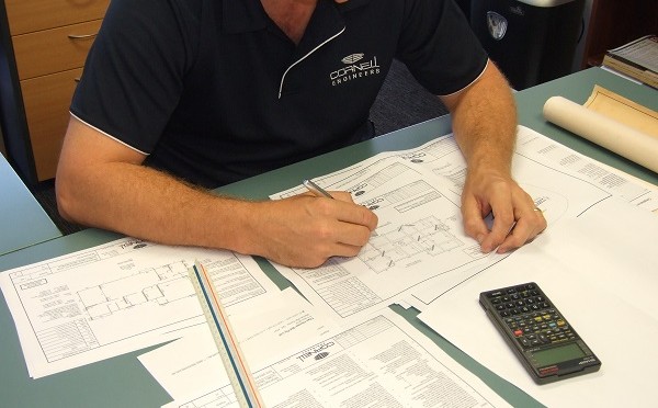
Join senior structural engineer, Matt Cornell from Cornell Engineers, as he checks a set of drawings for a single storey concrete masonry (Besser block) home to be built in a cyclone region.
He goes through the process of checking a set of structural engineering drawings with some tips for checking and good construction.
Today we’re going to go through the process that I normally
follow when I’m checking a set of engineering plans.
So a job comes into – a set of plans come into the office and they’ve asked us to do the engineering.
One of my engineers has done up some engineering drawings.
Here you can see the engineering, the AutoCAD file. They’ve set up a Form 15 ready for me to fill in. I’m doing the checking.
So a lot of the work has already been done. There’s a checking folder already as you can see, so the first thing I’m going to do is to check to see what the client has asked for.
We’ll open up that email and here it is. An email came into our quotes folder. It says:
Dear Cornell Engineers, can I get you to do the engineering for this house, please? I need it as soon as possible. (typical) I have attached the floor plans, truss plans and soil tests. Let me know if you have any questions.
So see there are the attachments. The sample house, truss plan, the soil report, house plans and the truss reactions.
Let’s just close that for a minute. We’re going to go back and have a look.
The system inside our office is that when we receive these plans, we put them into the “Received” folder – that way we know that the latest plans are always in the “Received” folder.
Those attachments have been saved in here so let’s have a quick look at the house plans.
Looking at the house plans we can see that it’s a sample house. There’s a set of notes, some more notes, a site plan.
You’ll realise that some of the details have been removed from this set of drawings for privacy and that this job is a little bit old so some of the standards that have been referenced on these drawings are probably out of date now. However, for this exercise, it’s a pretty clear indication of what sort of plans we get.
Here we have a floor plan.
We can see that there’s a garage. It has one, two, three, four bedrooms with an alfresco, meals area, family room.
This is quite a nice house.
You can see this hatching around the outside walls – which indicates concrete masonry (Besser Block) external walls. If we zoom in here we’ll see that the walls have been dimensioned as190 thick – that’s a 200 series concrete masonry block wall and that’s pretty consistent around the outside of the house except for the alfresco.
There’s a downpipe there, but there’s a timber post in that corner. Let’s see what else we’ve got in this set.
This is the window layout so maybe there’s a bit more information on the windows on this plan compared to the previous plan.
The elevations show us what the building designer wants the house to look like when it’s finished.
The important things for a structural engineer in these drawings are a) how high the walls are (and that’s the garage so don’t forget that number is for a set down slab so 2.44 meters or two thousand four hundred forty millimetres to the ceiling height) and this is the elevation although the line doesn’t line up with anything. That’s the ceiling in behind and that’ll become a little bit clearer when we get to the cross-section.
So four elevations front, rear, left and right elevations and we
can see also that the roof sheeting is metal and there are windows and doors. That’s all fairly standard.
Here we go with the cross-section. So this is the building designer’s indication of the trusses – won’t necessarily be true – we have some information from the truss designer. We’ll use that in preference to how the trusses are actually shown but as far as the ceiling height, here we go at two hundred and forty millimetres from the slab is there so that’s how high when you’re standing on the slab that’s how high the ceiling will be.
The internal walls he says are 70mm pine stud frames. The outside walls we know already are concrete masonry, 190 core filled concrete masonry blocks. Okay
and what else we got going on. So that’s pretty much the last page of this set. This is an abbreviated set for this example. Um so let’s see what else we’ve got.
The Soil Test and AS2870
Here’s the soil test and remember a lot of the stuff, their private information, has been removed from this report.
So scrolling through and again this is an old soil test and some of
the ways the soil testing were done have changed a little bit in this time.
In any case, so the soil test has given us a photo from the street to help us confirm that this is the right allotment. They’ve given us the site address back on this previous page which you won’t see because it’s been removed for privacy and they’ve done some soil testing and they’ve actually, in this case, used Atterburg Limits which are liquid limit, plasticity index and linear shrinkage to classify the site – to determine how reactive the clays are on this site.
Those numbers are important to us but not as important as the site reactivity. The soil tester estimates that seasonal changes in moisture content are in the order of 20 to 40 millimetres. This is a moderately reactive site. The logs show there’s at least 100 kPa allowable bearing capacity so it’s nice firm soil and they’ve called it a class “M” site to AS2870-2011. So there we have class and moderately reactive site.
There’s some information on the profile so when they did the testing here’s what they found as they dug down to the depth that they went to – two meters. Borehole termination at two meters and there’s the profile. So the top 200 millimetres is silty sand fill overlying sandy gravelly clay fill, silty sand – alluvial and sandy clay – alluvial so natural soils down starting at about 500 millimetres depth
Second borehole because they need to do to both of them should be in the footprint of the house silty sand fill overlying sandy gravelly clay fill overlying sandy clay so it reviewing this information as a matter of course as structural engineers at the end of the day we’re relying on the soil test but we’d like to make sure as much as possible that the information that we’re using is correct and if we see a discrepancy we’re going to bring it to the soil testers attention.
So they’ve done some testing on this material they have done a particle size distribution, they provided an aerial photo with the location of where those boreholes and we’ll see that those bore
holes are within the footprint of the building and then there are just some standard notes.
Okay so I’m looking at a Class M soil test and the only other thing
we haven’t looked at is truss plan and here it is.
Nice colourful one but the thing and you can see the outline of the building. They’re relying on those outside walls, those concrete masonry walls, as the load-bearing walls and also as the tie-down walls for and some cases where it’s unclear where big trusses are spanning across the building and they’ve used the walls of the alfresco.
They’ve also nominated these walls will be load-bearing as well and
they become a little bit more apparent when you see those X’s across the wall so they’re internal tie-down points on internal walls and here is another one but this one’s a timber wall so a load-bearing wall, some X’s showing that these trusses are sitting on to those walls here’s the third one we’re going to take that into account when we do our checking of the drawings to make sure our engineer has taken all that into account.
So this is now ready for checking. Let’s see where we’ve got those checking drawings in the checking folder. Okay, we’re going into the checking folder now so the AutoCAD drawings are there, the Form 15 is ready. We’ve gone through the received and the emails. Now we’re ready to start going through our engineering drawings.
So let’s open these up. A quick run through the drawings that Cornell Engineers provides for a single-story concrete masonry house. This is a house in a cyclonic area, a Region C area but let’s just have a quick look at the layout of the plans.
First is our project-specific notes and rather than call these standard notes we call them project-specific notes because every note is read and checked to make sure that it’s relevant to this site and we’ll come back to this.
Some notes on safe design for the building contractor and
the homeowner to take into account to ensure that the Builder and the site remain safe. That’s just part of workplace health and safety and how we contribute to that.
Okay, so sheet S4 is our footing and slab plan and shows the layout of the footings and slabs and how thick the slabs are. We’ll come back to that as well.
We have one page of details. This tells the Builder and the concreter exactly how we want those footings laid out and how we want them built.
The bracing plan is essentially the wall framing plan with some extra notes on where the bracing is. So these areas the hatched walls are going to be plywood bracing walls and then there’s some tie-down or hold up details but cyclone areas mainly tie-down details so there’s a lot of emphasis on tie rods and then finally some bracing details.
So as checkers we’re going to start at the top and work down.
We’ll start with the very top thing which is the roof sheeting which we don’t need to check but the next thing that’s supporting the roof sheeting is the roof battens.
So we’ll have a quick look at the note for the roof battens. 35 by 70 MGP12 roof battens at 600 centres and there’s a connection which is a batten screw to each truss. That looks good.
Next, we specify the trusses. They’re being designed by the truss manufacturer and we’ve already seen those plans.
If a different truss manufacturer is used that’s fine but we want them to use an internal pressure coefficient of 0.7 and minus 0.5 and the truss manufacturer is going to do the design of the truss to truss connections. Finally, the truss bracing is going to be specified by the truss manufacturer and the ceiling is going to be pine battens.
Then there are some notes for the wall framing. We’ve shown the load-bearing walls, the walls that are helping support the roof – we want them to be 90 wide so we specified 35mm x 90mm frame which is essentially about a 4-inch frame in the old terms.
We’ve got tie down specified – M12 tie rods beside openings, corners, 900 maximum centres. We have non-load-bearing walls, these other walls that aren’t taking load including the bracing walls actually can be 70mm studs and the MGP10 is a slightly lower specification for strength.
For the timber studs because they’re non-structural. They’re not holding up any roof. This is the bit that explains what the hatching on the walls is. That’s the bracing walls and we talked about the capacity of 6.4 kilonewtons per meter and then we say that we want the builder to connect the bracing walls to the roof frame and that is using the details on the last page. So that’s that little bit covered.
We’ve got a single-sided plywood bracing wall detail for 6.4 kilonewtons per meter how thick the plywood has to be how it’s
nailed off so that’s all really good and how the builders got a few options here for how he can connect this bracing wall to the roof frame so I’ve got that covered as well so good work by the guys because we know it’s 200 series concrete masonry walls we know that the builder is going to need details on how to connect the roof trusses by the trust manufacturers to those concrete masonry walls and here are our details. This shows how we would like the building to connect them so I’ve talked about threaded rods and talked about his picture of the plate that’s going to go over the trusses where there are roof beams we want them to bolt the roof beams to the concrete masonry wall using this detail. Where there are trusses to roof beams so out on that Alfresco area well we want them to use a looped strap to connect the trusses to the roof beam.
We know that there are some internal load-bearing walls so here we have a detail for tie rods running down the middle of the wall of the load-bearing wall and connecting the bottom chord of the truss which is where the truss manufacturer allows us to connect to and when there’s an internal concrete masonry wall which is that wall on the alfresco – that’s the detail we want the Builder to use and finally there’s a detail here for how we want the framing tied down because it’s so important to get load from the roof down to the ground.
We show the load path not directly but it’s all there so a truss or a rafter sitting on the wall is connected to the lintel which connects out to the outside beside the opening through a tie rod for uplift down to the slab and then a couple of studs jamb studs they’re called beside the opening to hold the roof up over that area.
The last one we haven’t checked how to look at is this alfresco roof beam to a timber post so going back a page here’s that connection we’ve got a post in the middle a post on the outside edge we’ve called up that roof beam size there’s an rb2 it’s 195 by 65 Hyne beam roof beam the rest of the openings.
Besser Block Walls
Around the external concrete masonry Besser block walls, the drawings have called up a bond beam – BB116S. There’s also a BB216S for the big garage opening which is a bit wider.
We’ve got a detail that shows how to build the bond beam – it has two sixteen millimeter bars top and bottom.
Here’s the information the builder needs to build where the timber frames are but the outside perimeter Besser Block walls – we don’t want there to be any movement.
In fact we want there to be a good amount of strength transfer between the timber frames and the concrete masonry walls so we’ve told the builder to fix the timber frames to the concrete masonry walls with one M12 Chemset which is an M12 epoxy bolt that’s glued into the concrete masonry at the top of this wall and also at mid-height. That’s going to stop those walls moving around independently of each other
That is pretty much our standard detail – we expect to see those bolts on all these internal walls where abut the perimeter Besser Block walls.
You can see there’s another post in the middle of the the entry roof and a roof beam size so going through checking this I would give that a quick check to make sure I’m comfortable with that size and finally I can see there’s an l1 size here so I imagine that there’s an internal load-bearing wall lintel and that would be built according to that lintel detail for the timber which is this one little tie-down detail on this next page and that actually looks like a cavity slider so that’s a bit tricky that l1 has suspended right across over the top of cavity a little trick for um for those who aren’t used to checking these sorts of things so this layer I’m pretty comfortable that the guys have got the floor plan the walls all pretty much in the same location as the building designer because we start with the building designers drawings when we put these plans together we actually copy the building designs information into our plans and sometimes we actually overlay these two claims just to make sure they all work so well I’m pretty confident are the same as the building design or in a full design check I’d probably do a quick check to make sure we’ve got all the openings in the right spot and that we’re referring to the latest set of building designers plans we’ve got doorway in the entry we’ve got some the lintels over the openings I’ve got got roof beams out in the alfresco area and posts and the post size has been called up there so that’s really good so I think British pretty happy with this bracing plan so we’re working our way down and the next thing we’re going to check is that slab plan so let’s get and zoom out of here and head over to the slab plan so now this is a class-“M” site and the engineer has done a great job of identifying this is an M site and the requirements according to AS2870 things that are really important to us to make this house for the homeowner and for the Builder to observe to give this house the best chance to resist foundation movement ground movement and that’s a whole thing that we’ve got a lot of information of on that on our website so the main specification of the reinforcement in the concrete 200 series concrete masonry walls is here and we talked about bars where the vertical bars are which are these dots on the plan so each one of these dots is exactly where we would expect the vertical reinforcement to be placed in those walls on site. We want extra bars beside big openings this is how we specify the heavier bars the end 16 bars and I’d expect this probably some over beside the garage door which is a bigger opening it’s got a bit more load on it and don’t forget in cyclonic areas we’ve got a design for the loads from the garage doors bearing on these door openings so there’s a little bit of extra rinsed reinforcements and strength in around the garage door to strengthen the frame around the roller doors or the panel lift doors in this case probably these diagonal bars are crack control bars we call up as per AS2870 which is the low ductility
reinforcement placed at the reentrant cornice and we’ve got that required of that requirement rather wherever we’ve shown these three bars on the diagonal so one two three four five places the slab thickness is shown in the hexagon and the slab reinforcement is shown directly underneath. SL82 mesh is eight millimetre bars at 200 millimetre centres both ways and it comes in the sheet of fabric and you can buy that from Bunnings or your reinforcement supplier and that’s the specification the way that the builder is used to reading it so the 30 millimetres cover is how high in the slab that mesh needs to be. It needs to be 30 millimetres from the top of the slab and the sides. In the alfresco area which gets wet and dry and rained on and it gets hosed off we need a little bit more protection to the reinforcement. It’s the same reinforcement size but we need 40 millimetres cover which is 40 millimetres of concrete over the reinforcement before you hit the slab on top of the slab so strip footing depth we said has been calculated in accordance with the engineering principles rather than the straight team to comply principles and we can use that as structural engineers we’re allowed to use section 4 of AS2870. Structural engineer who knows what they’re doing in relation to these jobs a quick check if we weren’t recording I’d be checking the spacing of our internal footings our SF ones and so I have a quick look here we know that there’s a 4 meter spacing requirement to be 4 metres from the outside of a slab and we know that at changes in direction that we want strength internal beams running both ways. So here we know we want this edge beam to continue as a strip footing. The designer has done a great job of that and in this location
with this direction we want this EB one to continue as an SF one so again he’s done a great job there in all those locations and all these locations all these internal corners you’ll see an SF one coming off in one
direction and in the other direction that gives strength to that corner and
that’s a requirement of a is 2870 a lot of engineers have trouble with that requirement but it’s very simple where there’s an internal corner
like that we want bars to continue to provide the strength the continuity in fact of the SF one through to the EB one and that gives the house again the best chance of performing well when there’s ground movement this is the set down on area this is the garage area remember and it’s set down a little bit lower than the house so that the homeowner can wash out that area if they want to so this is the symbol that we use to show that this area is slightly higher than the garage area of the garage is slightly lower than the main floor slab we’ve got another same sort of symbol out here in the entry slope but the house slab again is higher than the entry step.
so now a quick scan through all those details on a normal checking if wasn’t recording I’d be checking these EB ones the dimensions that we’ve provided for the SF one 300 by 300, in this case, it makes sure they’re aligned on the main part of the plan the set down dimensions there’s two types SF2 and SF3 where the patio is.
We’ve called that EB2 where they saw cut joints where there are shower rebates and I don’t think I mentioned that but they’re shown in these locations so in the middle of the slab according to the floor plan there’s a shower in this area and we’ve actually made the slab a little bit lower there and that’s the detail finally where we want BB 1 to continue as SF1 we’ve given a detail for that as well so the engineer has done a really good job on this one.
Finally we just kind of make sure that these project-specific notes are specific to the project so in this case some of the information has been removed for the recording but we’ve given the lot and plan number. The site has some fall it’s not it and we’ve asked the Builder to refer any problems to us. There’ are no overland inflows, The house is not near trees. The site conditions are as per the soil test and that there aren’t any sewer mains adjacent to the building
Notes for the concrete masonry are here. We reference AS3700-2011 which was the Australian standard and the year applicable at the time this job was done.
We talked about the mortar classification the strength of the core fill and that we want the corners all bonded we talked about how we want the soil placed and compacted underneath the house including the sand and the fill this directly underneath the slab which as we saw in the details is a little bit higher than the natural ground. We talked about our requirements for the concrete. So it’s N20 slabs we’ve gone actually up a grade to N25 concrete. We talked about how we want the reinforcement or how the reinforcement has been shown diagrammatically we talked about the grades of steel and the Australian standards that they had to be supplied to and we talked about most importantly or one of the important things how to cure the concrete to give the concrete the best chance to perform to harden beef rather than cracking over here we have our notes for structure of timber and we’ve referenced reference is construction we talked about rejecting the wrong kind of timber abnormally green or split timber. We’re using MGP12 of joint group JD4 or better so now that timber supplier knows what kind of timber to supply. I’ve talked about bolts and screws that they’re all detailed in accordance with AS1720, talked about plywood that needs to be stamped as structural grade plywood. These couple of the notes bolts in contact with CCA which probably don’t doesn’t apply to this house and if there are no other details given if we haven’t given a detail on connection details or tie-down or how walls connected to each other then the Builder is to refer to AS1684.3-2010 the Australian standard for residential timber frame construction relevant at the time of this record the timeless job was done and then finally we’re checking to make sure that the wind speed is right.
So I know from local knowledge on this job that it was Region C it was in a cyclone area there’s terrain Category 2. There are no buildings around this. I beg your pardon, this building is partially shielded one or two buildings around it but the land is fairly flat. Topographic factor talks about how flat or how
much slope there is on land there’s no factor there’s no increase in wind due to topographic so it’s T0 and we’ve classified the site as C2 so the Builder now knows what the wind speed is for this building and you can check that to make sure the trusses are supplied correctly that the
glazing the windows are supplied for the correct wind classification and here we talk about that internal pressure coefficient that we had on the other page as well. The floors are designed on the balcony for 2 kPa which is about 200 kilograms per square meter the internal floor inside the house is designed for 1.5 kPa and the roof is designed for about 25
kilograms per square meter and the truss manufacturer is going to take that into account and make sure that he’s going to make sure he provides trusses that are strong enough to take 25 kilograms per square meter which is really just a maintenance load of builders working on the roof we don’t expect anyone to be living up there so there you have it we’ve started at the back of this set and we’ve worked away from from the top down we’ve worked through the roof through the walls through to the slab and then we’ve checked our project-specific notes to make sure all that applies and is relevant and correctly specifies how the Builder needs to build this house.
So we are just about done. The only thing that’s left now is for the RPEQ engineer to fill in the Form 15 which is the compliance certificate to say that the engineering complies with the Australian standards so let’s get clean this up a bit so don’t forget this is an old form 15 this is an old job in general and this form is actually being changed slightly but the information is pretty much the same we talk about what street address so the street address for the actual house, lot and plan which is the surveyors plan numbers and what local government area this building is being built in. These are the things that we are responsible and that we’re saying do comply the footings the slab the concrete masonry walls 10 posts wall frame we’ve spoken about all these
things the wall bracing the lintels over the windows the roof beams add in the patio the alfresco in the entry and how the roof trusses are being tied down to these to the walls for our single-story residents as shown on their drawings.
So that all looks great. The Australian standards that we’ve referenced in this design are these ones and these are all correct and current at the time that this job was done. We used the Concrete Masonry Association’s Single Leaf Masonry Design Manual.
We’ve confirmed here the wind speed. In case this piece of paper gets separated from the drawings the Builder can use this to confirm what the wind speed is for this building.
We’ve talked about the roller doors quickly but this is a whole different video that the door frames are compliant with AS4505 we talk about our drawings
This is what we’re certifying. These are the documents that we’ve used to consider this design:
- our drawings,
- the floor plans by the building designer,
- the soil tests site report
- the truss plan and reaction report
We leave this one blank and then I fill in my details. I work at Cornell Engineers our contact details will appear here I’ll sign in this spot and I’ll put in the date of the day that I sign this form. Then this form gets PDF’ed and sent to the Builder along with these plans and now that we’re happy with them we go over here, create a new folder called “Issued” – this is how we do it internally at Cornell Engineers.
We put the date in reverse date notation so 2016, zero five, one four is the 14th of May 2016.
We’ just move those plans in there didn’t do that very well did I okay so now those plans are in “Issued” and once I’ve signed that Form 15 this job is ready to go to the Builder and go get built but because this is an olde job the builder has already got this.